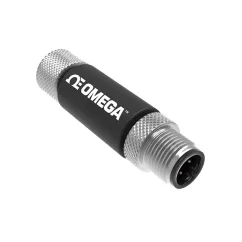
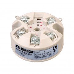
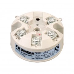
Miniature Head Mount Temperature Transmitter with RFID Communications

The TX401 and TX402 head mount temperature transmitters transform a temperature signal acquired from a Pt100, Pt1000 (TX401 only) or Ni100 RTD sensor or from a thermocouple (TX402 only) into a linearized 2-wire loop-powered 4 to 20 mA output. The characteristics of these converters ensure high precision on the reading scale with 16-bit conversion. The 4 to 20 mA output can be scaled based on the desired temperature input range.
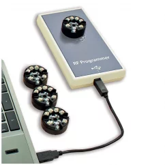
The programming procedure uses an RFID (NFC) mode with the dedicated TX400-RFID programmer that allows the user to make all calibrations and settings quickly and without the need to power and connect up the transmitter. Simply connect the TX400-RFID programmer to the USB port of your PC, start the RF Programmer configuration software and place the transmitter on top of the TX400-RFID programmer to establish communications.
An additional programming tool is the Omega Brand Google App - Direct Link relying on RFID/NFC connectivity and allowing straightforward programming without wirings by Android devices.
These temperature transmitters are also provided with a data logging function for the input signal. Transmitters have a non-volatile memory (circular buffer) for data-logging with user-selectable sampling time. The user selects the sampling time (1 to 3600 seconds) and then each time the 4 to 20 mA loop powers the device, the input value is stored to nonvolatile memory.
Using the TX400-RFID programmer along with the RF Programmer configuration software (software is a free download from OMEGA) the user can:
• Completely configure the transmitter including scaling the 4 to 20 mA output to desired temperature input range
• Implement field calibration to compensate for gain and offset errors
• Download logged data to PC for visualization and printing
SPECIFICATIONS:
RTD Input Types and Ranges:
TX401, TX402: Pt100 (a = 0.00385), 2, 3, or 4-wire connection: TX401: -200 to 800°C (-328 to 1472°F), TX402: -200 to 600°C (-328 to 1112°F)
TX401 Only: Pt1000 (a = 0.00385), 2-wire connection; -200 to 800°C (-328 to 1472°F)
TX401, TX402: Ni100 (a = 0.00618), 2, 3, or 4-wire connection: TX401: -50 to 170°C (-58 to 338°F), TX402: -60 to 180°C (-76 to 356°F)
Thermocouple Input Types (TX402 Only): J/K/T/E/R/S/B/N/mV
Output Resolution: 1 µA
Over-Range Output: FS + 5°C
Under-Range Output: FS - 5°C
Output Error (Failure): Selectable: TX401: between 21.5 or 3.8 mA, TX402: between 21 or 3.8 mA
Current Output Protection: 30 mA approx
Rejection: 50 to 60 Hz
Maximum Transmission Error: 0.1% FS or 0.2°C whichever is greater
Sampling Time: 300 msec
Response Time (10 to 90%): 600 msec
Non-Volatile Memory (Circular Buffer) for Data Logging:
TX401: 3966 Data Points
TX402: 2546 Data Points
Cable Resistance: 20Ω max
Temperature Coefficient: <100 ppm
Power: 2-wire loop powered; operating range 6 to 32 Vdc
Isolation:
TX401: Non-isolated
TX402: galvanic, 1 KVac input/output
Operating Environment: -40 to 85°C (-40 to 185°F), 30 to 90% RH (non condensing)
Storage Temperature: -40 to 85°C (-40 to 185°F)
Mounting: DIN/B head
Enclosure Material: Nylon (PA66)
Enclosure Rating: NEMA 1 (IP20) according to CE, EN 61000-6-4, EN 61000-6-2
Programming: Wireless with RFID technology (NFC)
Software: Windows® XP/7/8 (32-bit and 64-bit), Windows 10 (64-bit)
Connection: Screw terminals
Weight: 30 g (1.05 oz) approx
Dimensions: 23 H x 45 mm dia (0.9 x 1.77")
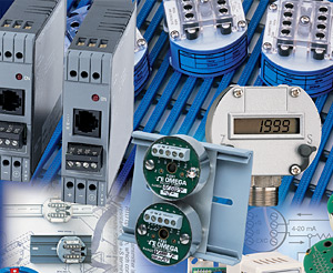
What is a Signal Conditioner?
A signal conditioner is a device that converts one type of electronic signal into a another type of signal. Its primary use is to convert a signal that may be difficult to read by conventional instrumentation into a more easily read format. In performing this conversion a number of functions may take place.
Signal conditioning is a vital process performed within the Data Acquisition System. It involves the manipulation of the analog signal output from the sensors to prepare it for the next stage of processing. Signal conditioning amplifies and converts the signals from the sensors or...
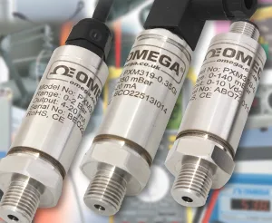
Understanding Sensor Output Signals
Have you ever wondered why there are a multitude of sensor output signals that can be configured on pressure, temperature, humidity, or gas sensing instrumentation used in process or HVAC applications? Most of these offerings were originally set up to allow sensor manufacturers to better align with the inputs offered by manufacturers of programmable logic controllers (PLCs) and direct digital controllers (DDCs), which are used for controlling processes for both automation and HVAC control.
I’d like to focus on two of the most commonly used output signals and zero in on the advantages and disadvantages...
Accessories1
TX400-RFID
Related products7
Thermocouple Input Temperature Transmitter with Pushbutton Config
In-Head Mount RTD Pt100 transmitter with 4-20ma output
Load Cell and Strain Gauge Amplifier and Transmitter
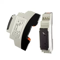
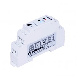
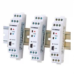
DIN Rail Mount Transmitter with RFID Communications
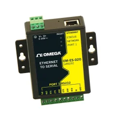
Ethernet to RS232 Serial Device Server 10/100Base
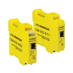
Industrial Ethernet to RS232, RS485/422 Serial Device Servers