Thermocouple Input Temperature Transmitter with Pushbutton Config

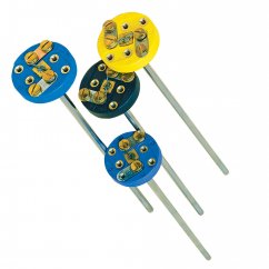
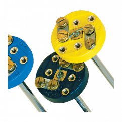
The TX13 in-head mounting thermocouple transmitter converts a thermocouple input over a configured range to a standard industrial (4 to 20 mA) transmission signal. A simple push button operation allows the user to select thermocouple type, burnout direction, select fixed ranges and trim 4 and 20 mA points. The in-head transmitter incorporates the latest digital technology to ensure accurate drift-free performance.
The default factory scaling is for a range of 0 to 1000°C and Type K thermocouple input, with up-scale burnout. Upon request, we will set up a transmitter according to your specifications.
SPECIFICATIONS:
Isolation: Tested to 250 Vdc
Sensor Burnout: Either up or down scale output
Cold Junction:
Range: -40 to 85°C
Accuracy: ±0.5°C
Tracking: ±0.05°C/°C
Stability:
Offset: 0.1°C/°C
Span: 0.05°C/°C
Accuracy@20°C:
| Sensor | Range °C | Input Accuracy |
| K | -200 to 1370 | ±(0.5°C + 0.1% of F.S.) |
| J | -100 to 1200 | |
| E | -200 to 1000 | |
| N | -180 to 1300 | |
| T | -200 to 400 | |
| R | -10 to 1760 | ±(0.5°C + 0.1% of F.S.) over the range 800 to 1600 |
| S | -10 to 1760 | |
| mV | -10 to 70mV | ±0.02% of full scale |
Output Type: 2 wire, 4 to 20 mA sink
Output Connection: Screw terminal
Maximum Output: 21.5 mA (in high burnout condition)
Minimum Output: 3.8 mA (in low burnout condition)
Accuracy: (mA out/2000) or 5 uA (whichever is the greater)
Loop Voltage Effect: 0.2 uA/V
Thermal Drift (from 20°C): ±1 uA/°C typical; ±1.5 uA max
Maximum Output Load: [(Vsupply-10)/20]KΩ (Example: 700Ω @ 24V)
Environmental
Ambient Operating Range: -40 to 85°C
Ambient Storage Temperature: -50 to 90°C
Ambient Humidity Range: 10 to 90% RH non condensing
Physical Dimensions: 43 mm Dia; 21 mm H
Weight: 31 g (encapsulated)
Update Time: 500 mS
Response Time: 1 second to 90% of final value
Start Up Time: Typically 5 seconds from power up
Warm-Up Time: 1 minute to full accuracy
Power Supply: 10 to 30 Vdc
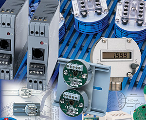
What is a Signal Conditioner?
A signal conditioner is a device that converts one type of electronic signal into a another type of signal. Its primary use is to convert a signal that may be difficult to read by conventional instrumentation into a more easily read format. In performing this conversion a number of functions may take place.
Signal conditioning is a vital process performed within the Data Acquisition System. It involves the manipulation of the analog signal output from the sensors to prepare it for the next stage of processing. Signal conditioning amplifies and converts the signals from the sensors or...
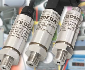
Understanding Sensor Output Signals
Have you ever wondered why there are a multitude of sensor output signals that can be configured on pressure, temperature, humidity, or gas sensing instrumentation used in process or HVAC applications? Most of these offerings were originally set up to allow sensor manufacturers to better align with the inputs offered by manufacturers of programmable logic controllers (PLCs) and direct digital controllers (DDCs), which are used for controlling processes for both automation and HVAC control.
I’d like to focus on two of the most commonly used output signals and zero in on the advantages and disadvantages...
Related products7
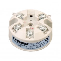
In-Head Mount RTD Pt100 transmitter with 4-20ma output
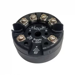
Miniature Head Mount Temperature Transmitter with RFID Communications


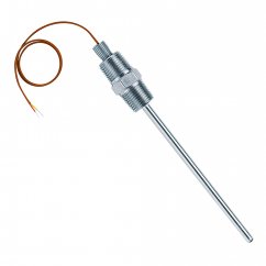
Industrial SuperOMEGACLAD™XL probe with NB3 head

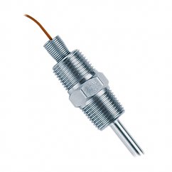
Industrial Super OMEGACLAD™XL probe with NB12 head

DIN Rail Mount Transmitter with RFID Communications
Replacement Thermocouple Probes for Protection Heads